
|
It is currently Tue May 14, 2024 10:14 pm |
|
All times are UTC |
|
|
Page 1 of 1 |
[ 3 posts ] |
| Print view | Previous topic | Next topic |
EZNEC Tutorial #008 - Using Loads to model a trap dipole
|
Silent Key
|
In this tutorial we'll look at how to build a 2-band trap dipole; along the way we'll learn how to model the traps and what losses they incur.
Start by loading up the original 20m dipole example: http://www.karinya.net/g3txq/temp/ez_tu ... ez001_1.ez Double-click the file to run EZNEC and open up the main Control window. ---------------------------------------------------------------------------------------------------- Before we go any further:- * Place the antenna over real ground: >Ground Type > Real > High Accuracy > OK * Use some real wire: >Wire Loss > Copper > OK We're going to build a 20m/40m trap dipole. A monoband 40m dipole would have a length of about 66ft, but the loading effect of the traps will mean we need a significantly shorter wire - around 58ft - so open the Wires window and change the X dimension of End 2 from 34 to 58; the window should look like this: 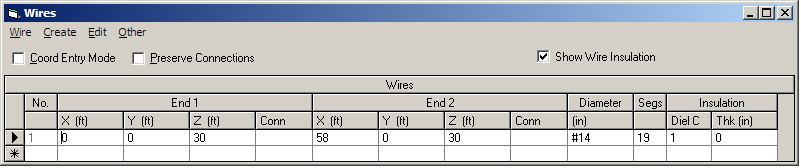 Now we need to insert the two traps, but EZNEC has to be told the electrical characteristics of the traps - their inductance, capacitance and series resistance. Let's assume we are going to use a couple of coax-wound traps. Using the VE6YP caluclator we find that 6.3 turns of RG58 on a 1.5" diameter former would resonate in the middle of the 20m band (14.150MHz) and would have equivalent component values of L=1.43uH and C=88pF. Unfortunately the calculator gets this totally wrong by a factor 4, and the real values are L=5.7uH and C=22pF. If we assume a Q for the trap of 200, the series resistance will then be 2.5 Ohms. We now know some trap parameters for the model but we don't know exactly where to place them on the wire, other than that they will be symmetrical about the centre. We would expect them to be about 34ft apart because that's the length of a 20m dipole, so they would need to go at positions 20% and 80% along the 58ft wire. Unfortunately because we are limited to 19 segments on the free version of EZNEC we wont be able to place the traps exactly where we want them - each segment is 3ft long and we can only put our traps at the centre of a segment - but we'll do our best! Open the Loads window and for Load1 specify Wire# as 1, and %FromE1 as 20. Click Other>>ChangeLoadType... and in the ChangeLoadType window select the RLC option and then OK. In the LoadConversion window select Parallel and then OK. These steps tell EZNEC that we want to specify the trap in terms of a Resistor, Inductor and Capacitor in parallel form. Back in the Loads window enter 2.5 for R, 5.7 for L and 22 for C. Then click in the RFreq box and select 14.05 from the drop-down menu. Finally, click in the Config box and select Trap from the dop-down menu. Check that the final ExtConn box is showing Ser. These steps have placed a trap with the required RLC parameters 18.4% the way along the dipole; the trap is in series with the wire, and the 2.5Ohms resistance we have specified applies at a frequency of 14.05MHz. Now repeat for trap 2, but place it 80% the way along Wire#1. Your Loads window should look like this: 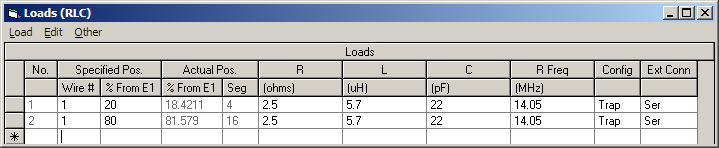 Open up the ViewAnt window and you will see where EZNEC has placed the traps - shown as red squares. Now let's see if we really have built a two-band 20m/40m trap dipole. Run an SWR plot from 13.5MHz to 14.5MHz in 0.05MHz steps. You should see this: 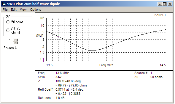 As you see the dipole is resonant at about 13.9MHz with a SWR just over 1.6:1. Because of the 19 segment limit, we can only move the traps around in 3ft steps, so it's impossible to move the resonance in-band, but you get the general idea! Now do another SWR scan from 6.5MHz to 7.5MHz in 0.05MHz steps, to get this: 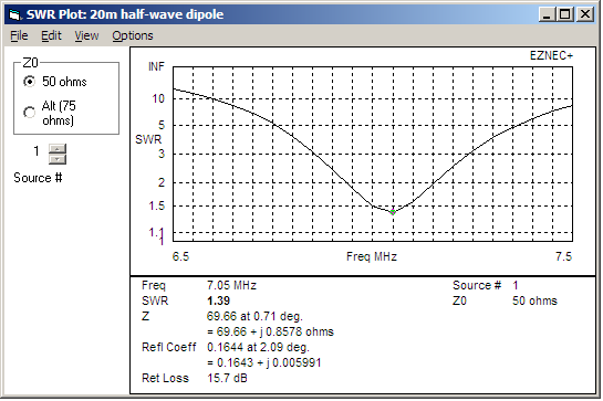 We get resonance at 7.05MHz with an SWR of 1.4:1 Finally, let's have a look at losses in the traps. For this, it's useful to drive the antenna with a fixed power rather than the more usual fixed current. To do this, in the Main Window select Options>>Powerlevel... untick AbsoluteV,Isources and enter 100 in the Powerlevel box to drive the antenna with 100 Watts; click OK. Now with the frequency set to 14.05MHz click LoadDat and you should get a window like this: 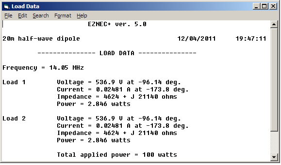 Here's lots of useful data about each trap - the power dissipated in them, the voltage across them and the current flowing through them. Notice that the power lost in each trap is about 2.8W, which gives a total trap loss of 5.6W or 0.25dB. Further things you can try for yourselves: * See what the trap losses are on 40m * Vary the 20m frequency and find the frequency where the trap losses are greatest * Change the R value of the traps and see what happens to the losses. 73, Steve G3TXQ |
| Tue Apr 12, 2011 7:15 pm |
|
EZNEC Tutorial #008 - Using Loads to model a trap dipole
|
Novice Member
|
Thanks very much Steve. That was very useful, as indeed are all the tutorials. I think I need the expert version to model my twin element multitrap dipole 10-80m.
You have managed to lift the veil on the wonders of Eznec. _________________ 73 de Mark MW0MAU http://www.mw0mau.net Dstar Hotspot MB6IMU |
| Wed Apr 13, 2011 8:03 am |
|
EZNEC Tutorial #008 - Using Loads to model a trap dipole
 ) and since the better weather is coming I can use this to help plan an antenna or 2 to suit my garden (and neighbours).
|
|
Page 1 of 1 |
[ 3 posts ] |
|
All times are UTC |
Who is online |
Users browsing this forum: No registered users and 1 guest |
| You cannot post new topics in this forum You cannot reply to topics in this forum You cannot edit your posts in this forum You cannot delete your posts in this forum You cannot post attachments in this forum |